
This guide provides step-by-step instructions for assembling the MBot Omni. The robot consists of three main components: the bottom plate, middle plate, and top plate. Each section is assembled individually before being joined together to complete the MBot Omni.

Bottom Plate
The Bottom Plate consists of motors, wheels and the control. This is where the low level sensing and actuation happens.

1. Assemble Omni Wheels
| Components Required | Qty |
| Omni-wheel Sets | 3 |
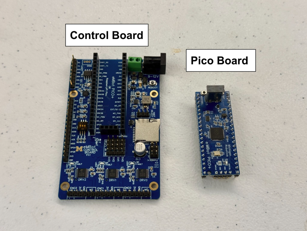
- Collect the Robotics Control Board and the Raspberry Pi PICO

- Attach the Pico board to the control board
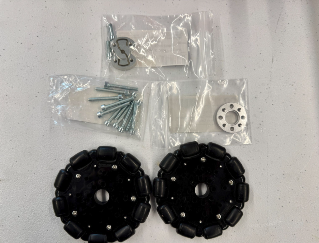
- Collect all the wheel components as shown in the image
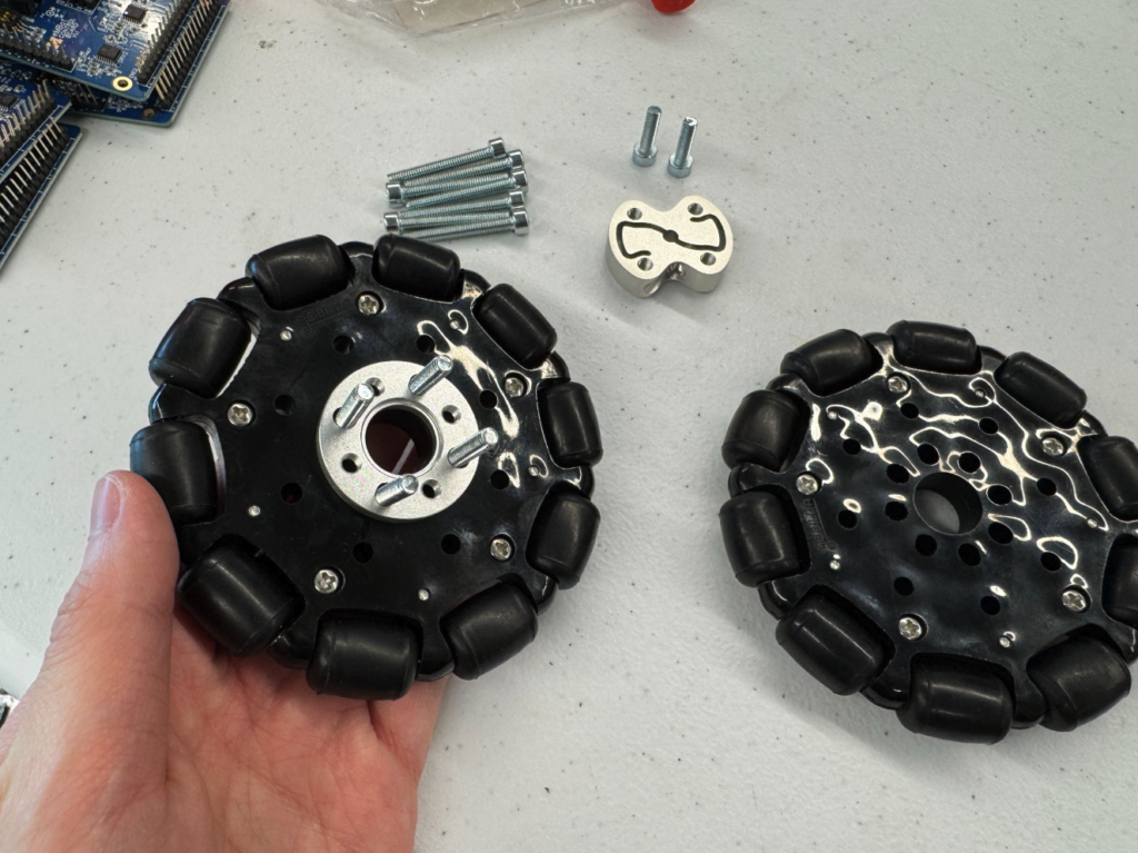
- To assemble the wheels, insert four long screws through the holes in the wheel
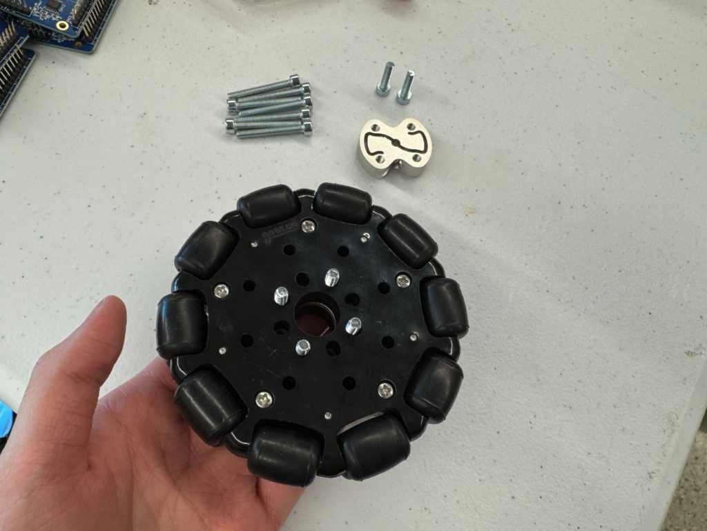
- Stack a spacer onto the screws, then place another wheel on top

- Add the coupler on top and tighten everything securely
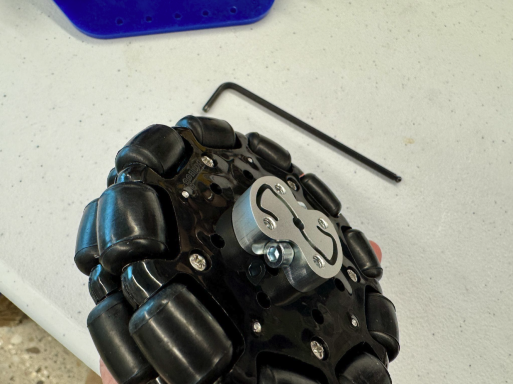
- Use a M3 hex key to attach two short screws into the coupler. These screws secure the wheel to the motor shaft
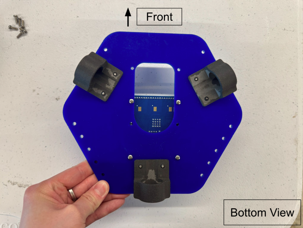
2. Attach Motor Mounts
| Components Required | Qty |
| M2.5 x 8mm Screws | 12 |
| Motor Mount (3D printed) | 3 |
| M2.5 threaded inserts | 12 |
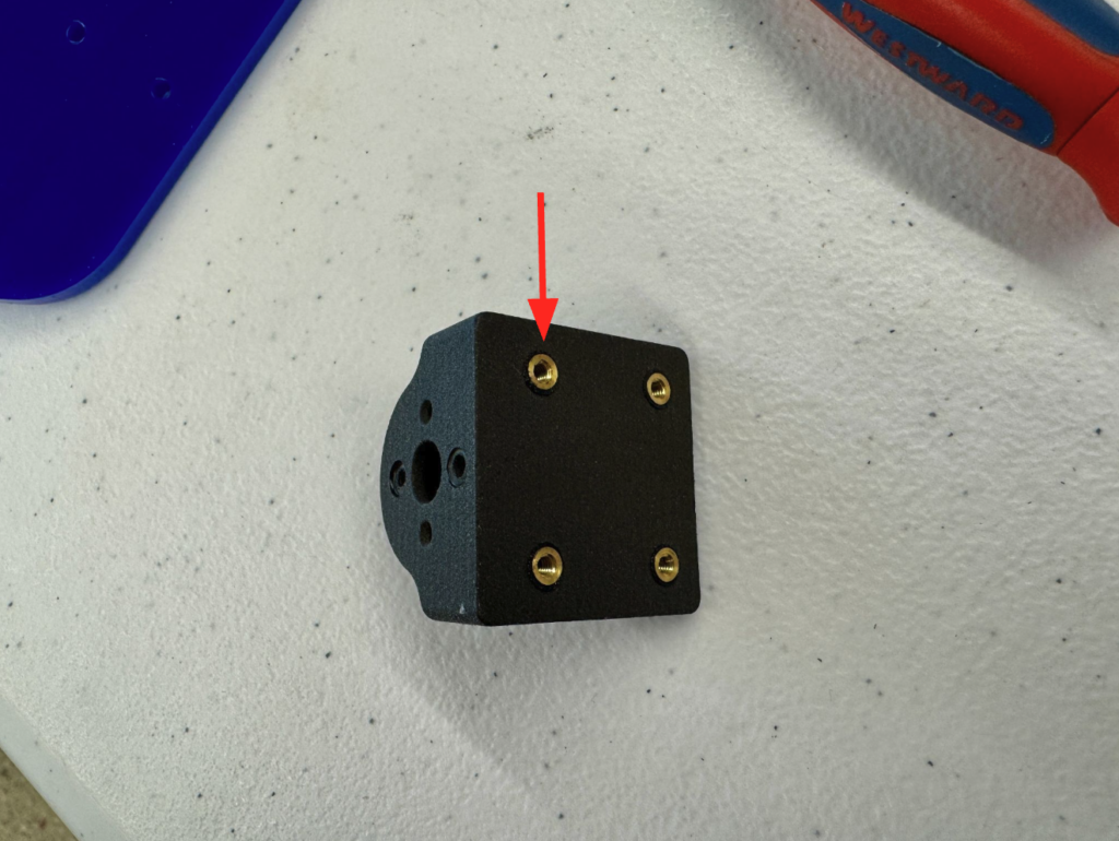
- Install the M2.5 threaded inserts as follows:
- Heat the inserts with a soldering iron until they can melt into the plastic.
- Push the heated inserts into the holes until they are flush. Let them cool and solidify before continuing.
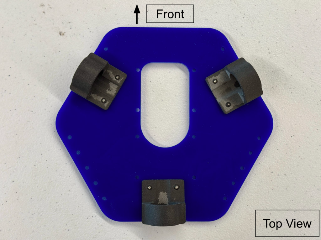
- Attach the motor mounts using M2.5 x 8mm Screws. When attaching the mount to the bottom plate, ensure that the slot faces inward.

- Flip the plate over for the next steps
3. Attach Robotics Control Board to Plate
| Components Required | Qty |
| Robotics Control Board | 1 |
| PICO Board | 1 |
| M2.5 8mm Nylon Standoffs | 4 |
| M2.5 x 6mm Screws | 4 |
| Jumper Shunt | 1 |
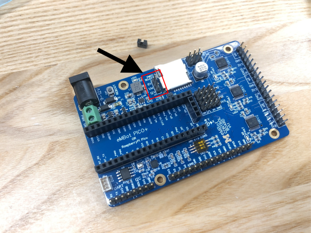
- Put the Jumper Shunt on 12V Power Pin of the Robotics Control Board.
- NOTE: The University of Michigan MBots fleet use 12V motors. You can choose a 6V motor if needed.
- Attach the Pico board to the Robotics Control board

- Attach the standoffs and screws, and secure them to the holes on the control board
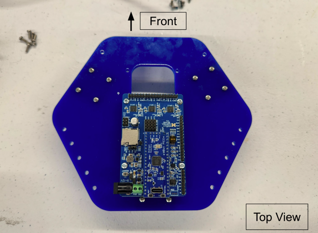
- Attach the control board to the bottom plate in the correct placement as shown
4. Attach Motors to Mounts
| Components Required | Qty |
| M2.5 x 6mm Nylok Screws | 6 |
| 12V Motors | 3 |
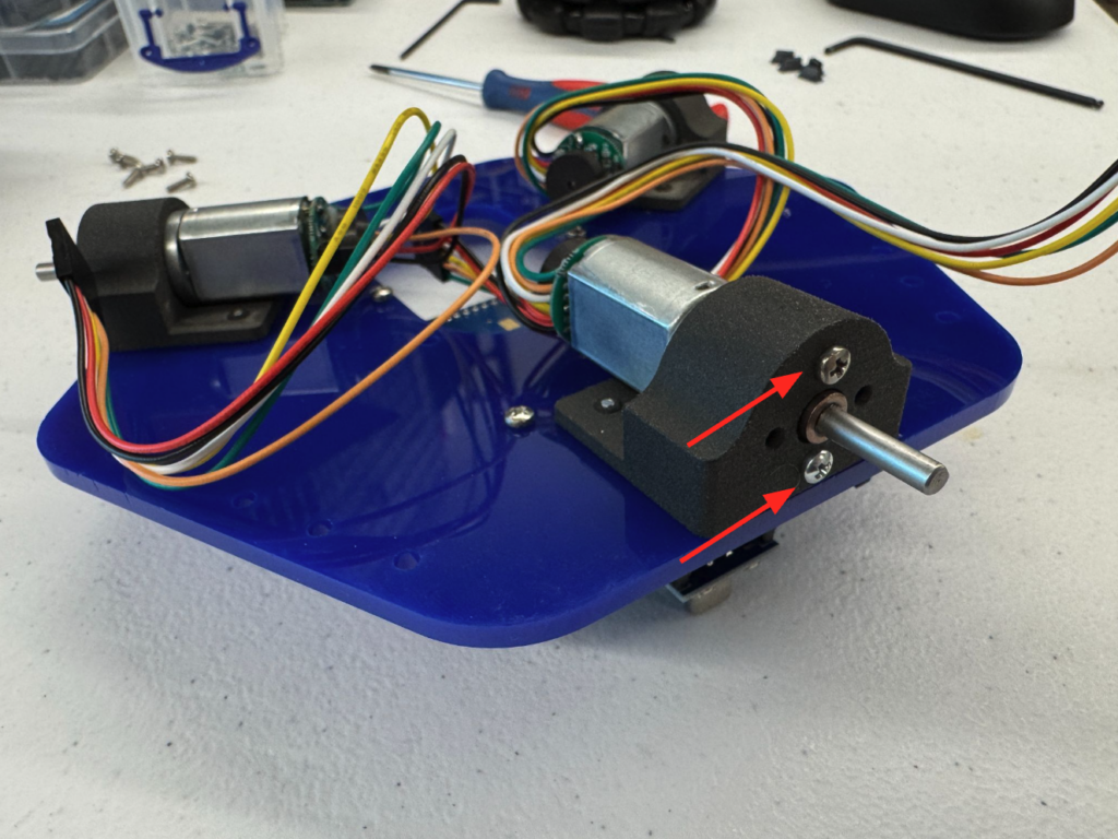
- Align the motor’s threaded holes vertically with the motor mount holes, secure the motor to the mount using two M2.5 x 6mm Nylok Screws. Repeat this process for all three motors.
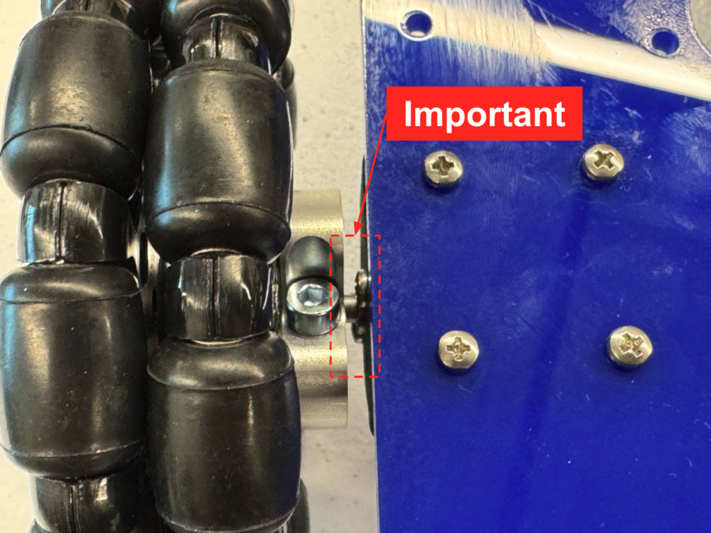
- Slide the 3 Omni wheel assemblies onto the motor shafts, leaving a nominal gap between the couplers and the motor mount screw heads
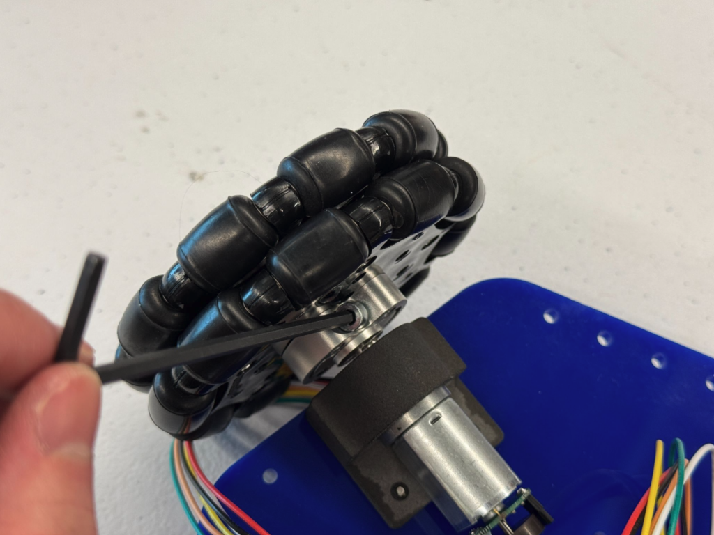
- Secure the wheels to the shaft the by tightening the two hex-head bolts on the coupler

- Connect motors to the control board by routing the motor wires through the cut-out in the acrylic plate and connect them to the pin-outs on the control board as follows:
- Right wheel → M0 slot
- Back wheel → M1 slot
- Left wheel → M2 slot
- NOTE: Make sure each harness is connected as shown in the image. The white pin must align with the GND pin, which is marked on the control board.
Middle Plate
The Middle Plate consists of the Raspberry Pi, Camera and battery.

1. Assemble control board and wheels
Top Plate
The Top Plate consists of the 2D Lidar